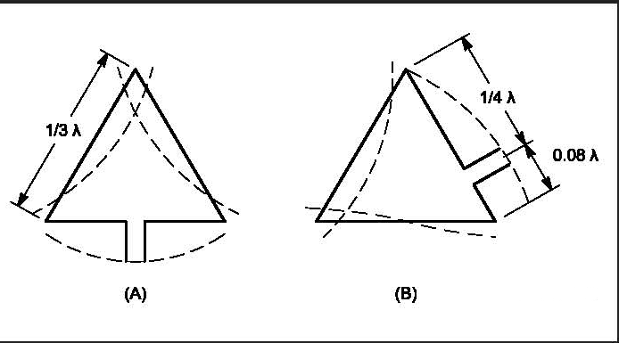
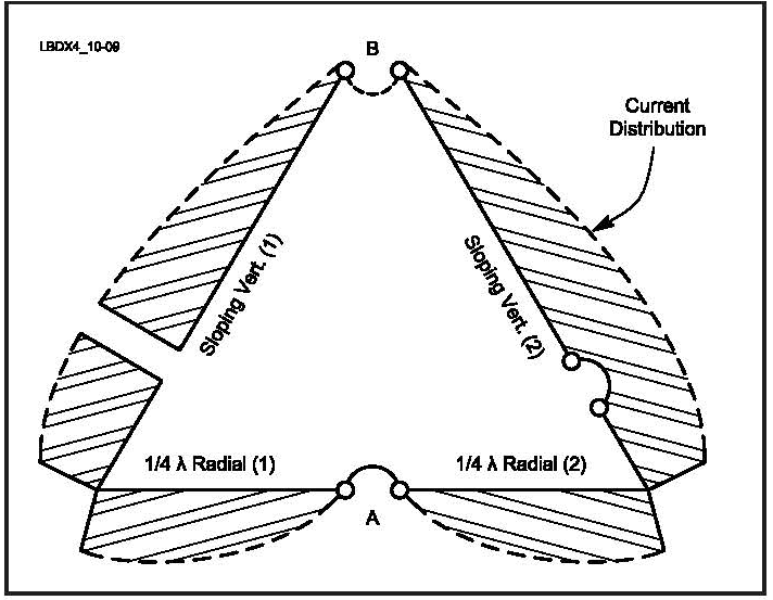
The radiation is verti-cally polarized and peaks in the plane of the loop. The 80 meter Delta Loop is mounted in a vertical plane.

Top Band Hams Vertical Loop Antennas
The horizontal loop vertical pattern stays relatively constant only decreasing in ground loss as height is increased.
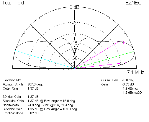
. Figure 2 shows the EZNEC comparative gains dBi and radiation patterns. This is a very realistic situation especially on 80 meters. Radiation Pattern in 2D.
Delta Loop Antenna Radiation Patterns. The base of the Delta Loop is only 10 feet above average ground. Maximum loop gain is 194 dB.
In 17 a novel vertical. The loop antenna displayed at the March GVARC meeting was in a vertical plane so the pattern in Fig. The feedpoint impedance of the 2 wavelength loop is around 260 ohms at the resonant frequency which is a bit lower than twice the fundamental.
Fig 4Calculated small loop antenna radiation pattern. ½λ vertical with a loading coil. In the shown polar diagram a quarter part of the circle with the antenna site as the origin the x-axis is the radar range and the y-axis the aims height.
Vertical antenna meaning that vertically polarized loops close to the ground will not work well over poor soil. Even though the low angle radiation may not be any better than a dipole an elongated loop narrows the vertical pattern and can reduce the strength of signals coming in at higher angles making it easier to hear the DX. Note the low angle of radiation.
The current at the grounded far end of the vertical element of the half delta loop is 097Z69 A. Some readers will note that this is close to the same length as the popular 58λ 43 ft vertical for 20m. By the time the loop.
The shape of the vertical pattern is a vertical cross cut of the three-dimensional graph. At low heights the gain for the loop is low and the radiation angles are high for both antennas but the loop is superior in every. A printed antenna composed of a dipole and a loop was proposed in 16 but it only achieved impedance bandwidth of 74 and low measured peak gain of 43dBi as well as not-so-good radiation patterns.
Characteristics of Small Loop Antennas for HF Operation Coupling loop 15 diameter of main loop for good impedance matching on all bands Antenna is narrowband operating at resonance of loop L and tuning C Radiation resistance in series with loss res. This null is very narrow and is. Ad Compact system no anechoic chamber needed.
Polarization of Loop Antennas HF DX signals are constantly changing in polarization The loop may be vertical or horizontal depending on feed point Vertical polarization is preferred when antenna is low DX rule is to feed the loop for low radiation angle Practical consideration is feed at ground level Select Feed Point to keep. 212 MHz Magnetic Loop Antenna Radiation Pattern - Vertical orientation 284 MHz Magnetic Loop Antenna Radiation Pattern - Vertical orientation 01 to. Vertical Delta Loop-Low height and low radiation angle -Portable and compact -No radials -Lower Noise -Essentially a mono-band antenna -Depends on ground quality -Very large on 80m and 160m.
Vertical Loop Antenna Polarization. The vertically oriented STL antennas -of-8 doughnut shaped radiation pattern figure maximum is in the plane of the loop with -farfield nulls for small loops at right angles to the plane of the loop. See Figs 4B and C.
H-plane represents the Horizontal pattern whereas V. Radiation pattern is vertically polarized and with nulls in the broadside directions. Would it have the same performance.
Fig 5Simple untuned small loop antenna. These resultant patterns are known as Horizontal pattern and Vertical pattern respectively. Fig 6Example of orientation of loop antenna that does not respond to.
Fig 10-3 shows both the azimuth and elevation radiation patterns of a vertically polarized quad loop with a top height of 03 λ bottom wire at approximately 004. This null progressively fills in as one makes the loop diameter larger. Note that the vertical pattern of a dipole changes radically as height is changed above 14 wavelength or 125 feet on 160 meters or 65 feet on 80 meters.
The antenna in this article at only 23 the height of a full ½λ vertical does just that. The resulting 3-D radiation pattern is shown in Fig. 4 - Vertical patterns and gains for the loop over the dipole antenna at various heights above perfectly conducting ground.
The two above pictures show the radiation pattern of the Delta Loop fed in the bottom corner of the antenna. The radiation pattern of a small loop is the same as that of a small dipole positioned perpendicular to the plane of the loop and located at the center of the loop as indicated in Fig. When looking through the loop from the side there is a deep null where the signal can be greatly attenuated.
A vertical loop makes a good NVIS antenna for the lower bands even if it isnt very high and feeding it at the bottom reduces the required feedline length. DX Wire Antennas Comparisons. Power divides between R rad and R loss Doughnut-shaped radiation pattern.
Figure 1B The far-field radiation pat-tern of a very small vertical loop in the horizontal plane. The loop is vertical in free space with the plane of the loop run-ning left-to-right. Since the currents on the vertical parts of the radiating system vertical wire and tower are approximately in quadrature you might expect a cardioid-like patternand this is what EZNEC predicts.
3 - Free-space vertical patterns for both antennas. -The wave emitted by the vertical loop may be polarized vertical or horizontal. Vertical plane loops tend to waste more radiation at high angles when they are 2 wavelengths or longer which limits their application as multiband antennas.
Two-dimensional pattern can be obtained from three-dimensional pattern by dividing it into horizontal and vertical planes. Loop curves are solid lines. The figures show the Omni directional radiation pattern in H and V planes as explained above.
Generally a magnetic loop will have its highest radiation inline with the vertical elements.

Top Band Hams Vertical Loop Antennas
Delta Loop Antenna Radiation Patterns Hy Power Antenna Company
Delta Loop Antenna Radiation Patterns Hy Power Antenna Company
Delta Loop Antenna Radiation Patterns Hy Power Antenna Company

Radiation Pattern Of The Loop Antenna Download Scientific Diagram
Delta Loop Antenna Radiation Patterns Hy Power Antenna Company
Delta Loop Antenna Radiation Patterns Hy Power Antenna Company

0 comments
Post a Comment